System Configuration and Communication Architecture
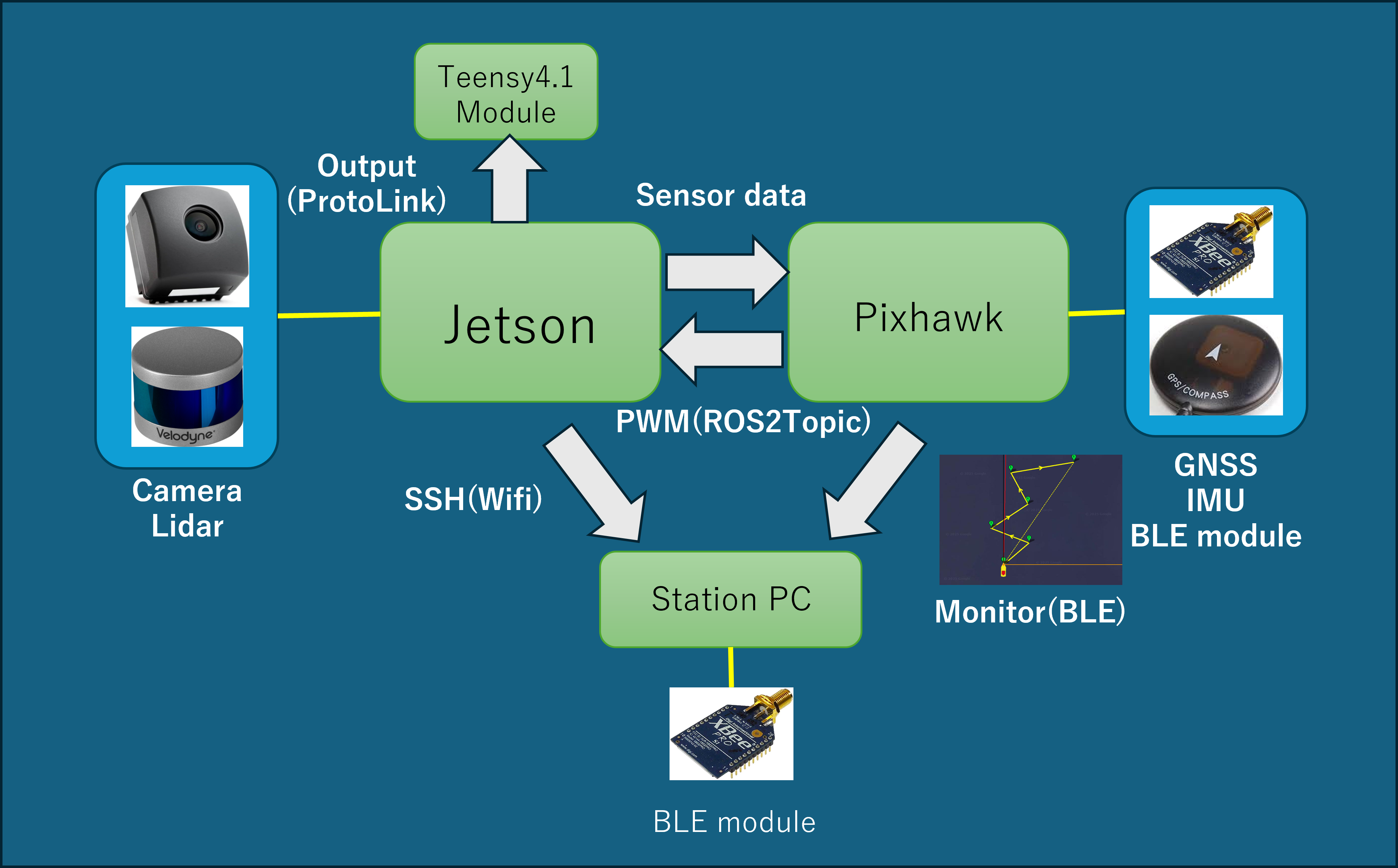
Fig 1. Software System
The Mini-V system is composed of the following elements to achieve both advanced information processing and real-time control.
Hardware Configuration:
We use “NVIDIA Jetson AGX Orin” for the main computer and “Pixhawk” for the flight controller.Communication Middleware:
We use “ROS 2 (Robot Operating System 2)” as the core of our software development. The system has a modular design, allowing multiple members to develop perception, control, and communication subsystems in parallel.Communication Automation:
To bridge the communication gap between the high-level computer running ROS 2 (Jetson) and low-level microcontrollers (motor drivers and emergency stop devices), we developed a proprietary mechanism called “ProtoLink”.- It automatically generates Protocol Buffer messages from ROS 2 message definitions.
- By using nanopb, it generates lightweight C structures compatible with Arduino and STM32 environments, realizing seamless communication without manual protocol maintenance.
Perception System

Fig 2. Image inference with YOLO
For environment recognition, we use a hybrid sensor fusion combining a camera and LiDAR (Velodyne VLP16). The processing flow is as follows:
- Visual Recognition:
We use “YOLO”, capable of high-speed real-time processing, to extract bounding boxes of objects from camera images. - Point Cloud Processing:
Simultaneously, 3D point cloud data obtained from Velodyne VLP16 is processed using a rule-based algorithm for clustering (classification by chunks). - Sensor Fusion:
By integrating 2D visual data and 3D point cloud clusters, we identify the “type” and “precise 3D position” of objects. - Costmap Update:
The integrated obstacle information is sent to Pixhawk and used to update the local costmap for avoidance.
Localization
Self-position estimation is mainly processed by the “ArduPilot” firmware running on the Pixhawk flight controller.

Fig 3. Pixhawk
Sensor Configuration:
GNSS (Global Navigation Satellite System) and IMU (Inertial Measurement Unit) are integrated into Pixhawk, and these data are processed with a Kalman filter to estimate self-position.Visual Odometry Integration:
In addition to GNSS and IMU data, visual odometry information (movement estimation by image analysis) sent from the ROS 2 main computer is fused to perform self-position estimation and PID control.
Planning & Autonomy
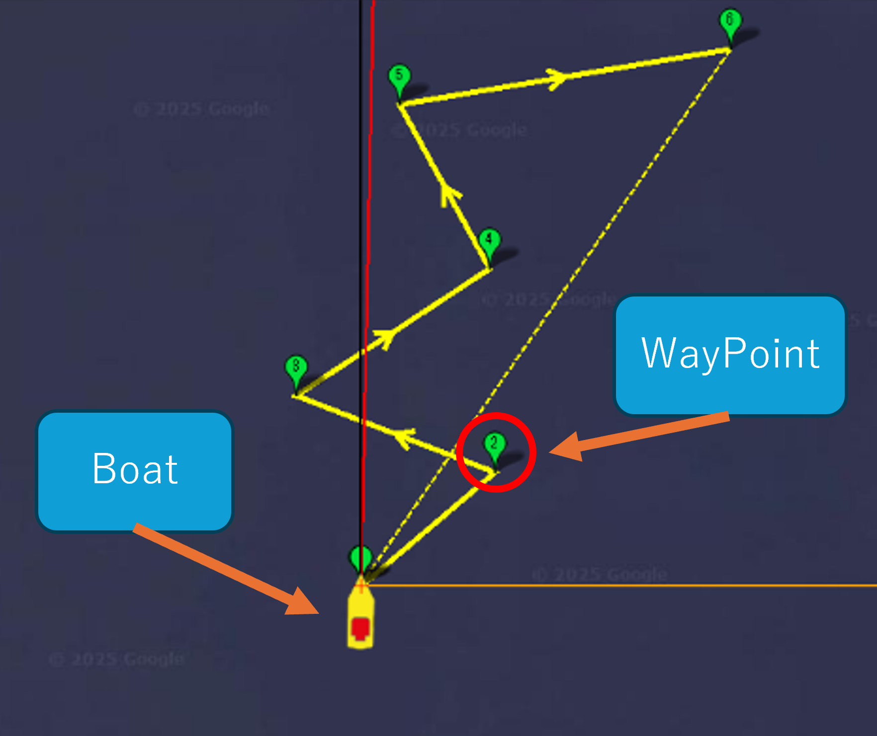
Fig 4. Simulation with Mission planner
Dynamic Path Generation Based on Visual Information:
Instead of running on a predetermined route, the route is calculated in real-time from environmental information captured by the camera and LiDAR.- Identification of Safe Passage Route: Detects markers on the left and right and calculates their geometric midpoint to identify a safe route to pass through.
- Automatic Waypoint Generation: Sequentially generates relative waypoints for the calculated target point and steers autonomously to the destination.
Obstacle Detection and Avoidance Function:
If there is an obstacle on the navigation route, the robot immediately recognizes it and takes avoidance action.- Spatial Recognition by Costmap: Information on recognized obstacles is immediately reflected in the robot’s “local costmap” (surrounding map).
- Circumnavigation/Avoidance: When an obstacle is detected, it identifies the position by verifying with GNSS information, and at the same time performs advanced control to avoid and circumnavigate while keeping a safe distance using LiDAR for distance measurement.
Precision Maneuvering Based on Situational Awareness:
It is possible to not only simply move but also understand external signals and dock shapes to perform complex actions.- Signal Analysis and Action Decision: Analyzes external signs such as light signals using image recognition, and based on instructions (color or pattern), can navigate to draw complex shapes such as clockwise or counter-clockwise turns.
- High-Precision Approach Control: In situations where docking to a quay or dock is required, it uses LiDAR ranging data to grasp the distance to the wall surface in units of several centimeters, and accurately approaches and stops at the designated location.
- Safety Verification via Simulation:
These complex autonomous behaviors are thoroughly verified in a virtual space before operating the actual machine. Through behavior confirmation in a field wider than the actual water surface using SITL (Software-In-The-Loop) environment utilizing Pixhawk and Docker containers, only safe software is deployed to the actual machine.